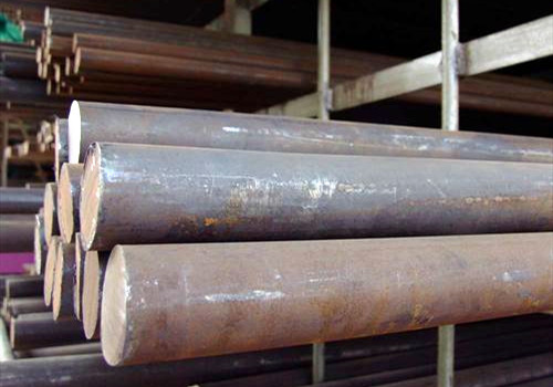
High strength steel ASTM A519 Gr.4130 is a medium carbon modulated Cr-Mo steel with excellent yield strength, tensile strength and notch toughness. The material offers a high carbon content, and the appropriate addition of Cr, Mo and other elements can improve its hardenability and anti-tampering softening tendency, which has been widely used in Marine high-pressure line tubes. Through chemical composition and simulation experiments, we found that the steel is prone to crack or embrittlement in a heat-affected zone during welding. There are the chemical composition and mechanical property of the steel:
| C | Si | Mn | S | P | Cr | Ni | Cu | Mo |
| 0.28~0.33 | 0.15~0.35 | 0.40~0.60
|
≤0.040 | ≤0.035 | 0.80~1.10 | ≤0.030 | ≤0.03 | 0.15~0.25 |
| Tensile strength (Mpa) | Yield strength (Mpa) | Elongation A% | Impact work (-40℃ kV /J) | Rockwell hardness (HRC) |
| 731 | 625 | 21.6 | 50.52.48.50 | 20 |
4130 steel pipe welding process is sensitive to welding heat input, too large heat input will cause the welding heat affected zone Austenite grain coarser, joint toughness and crack resistance decreased; small heat input making the cooling speed fast, the hardened tissue will be produced easily and increased the crack tendency. According to our experience and combined with the welding process, the heat input of TIG welding in this test should be controlled in the range of 1.5 ~ 2.0kJ /mm and that of manual arc welding should be controlled in the range of 1.8 ~ 2.5kJ /mm.
In order to obtain good weld joints quality, we suggest control the following items:
1) Control the hardness value of welding heat affected zone;
2) Control residual diffused hydrogen. According to the classification society’s regulations, low hydrogen welding materials (HDM≤5ml/100g) should be used for welding this kind of steel, so we used ESAB’s OK Tigrod 13.13 argon arc welding wire (AWS A5.28ER100S-g) in the test.
3) Control the rated low-temperature toughness of the joint (-20℃≥27J).
Preheat and interpass temperature
Preheating is one of the effective measures to prevent cold cracking. It can reduce hydrogen, improves tissue and reduces stress. AWS D 1.1 Annex Ⅰ suggests the preheating temperature of 120-150 ℃. The interpass temperature should be strictly controlled within the range of 150-210℃ in order to avoid weld overgrowth. Groove and bead layout are set like this:
Welding parameters
The heat input is the energy received by the weld per unit length, which is the main factor affecting the welding thermal cycle. That is to say, when the welding material and method are determined, the structure and performance of the welded joint mainly depend on the size of the welding heat input, and improper welding parameters will lead to the deterioration of the joint performance. Welding parameters were optimized according to the two-dimensional maximum hardness formula of heat transfer and heat-affected zone:
| Welding passes No. | wire diameter
(mm) |
Current
(A) |
Voltage
(V) |
Welding speed(mm/min) |
| 1 | 2.4 | 120-130 | 14-15 | 35 |
| 2-7 | 2.4 | 130-140 | 15-16 | 30-59 |
| 8-10 | 2.4 | 130-140 | 15-16 | 40-65 |
The experimental results show that the tensile test results also meet the requirements:
| Sample No. | Tensile strength(mpa) | Fracture position |
| 1 | 785 | Weld joints |
| 2 | 705 | Weld joints |
Welding Joints Test
Bending test
The bend test is a test of a material’s ability to withstand deformation. We test it in the WE- 100 universal testing machine with a sample for bending test according to the specification requirements, take four lateral styles with 5t (t) for the base metal thickness in bend test with an Angle 180°, no crack on the surface of the specimen after bending and there is no length is greater than 3 mm in any direction other defects, the experimental results meet the requirements.
Impact test
Impact test in JB-30B impact testing machine, with impact load to make the joint groove fracture, the impact energy consumed on the unit area can determine the impact performance of the welded joint. The impact test adopts -20° Charpy impact, sampling at a position 1-2mm away from the joint surface, the notch position is located in the weld center, the fusion line, the fusion line 2mm, the fusion line 5mm.
| Groove position | single impact value (J) | Average impact value |
| Weld center | 112,140,94 | 115 |
| Fusion line | 128,130,134 | 131 |
| Fusion line +2mm | 134,128,118 | 127 |
| Fusion line +5mm | 134,140,128 | 134 |


